")
")
")


")

ABSTRACT
A plasma gasification melting (PGM) technology has been developed to transform waste into synthesis gas and products suitable for construction materials. The core of the technology was developed at the Kurchatov Institute in Russia and has been used for more than a decade for the treatment of low and intermediate-level radioactive waste in Russia. It is applicable to municipal solid waste (MSW), municipal effluent sludge, industrial waste, and medical waste.
Plans are currently underway to build a plant in the US to recycle medical waste using the PGM technology into a high calorific Syngas and a benign residue. Both output materials may be considered secondary materials since they have commercial use in other processes. Current plans include the production of steam which will be sold as a commodity to nearby industrial users
The Syngas is fed into a Heat Recovery Steam Generator (HRSG) to produce superheated steam for use as heat or electricity generation using a steam generator. The exhaust gas leaving the HRSG will enter an Air Pollution Control (APC) system for post-process gas cleaning. The APC system will use a wet scrubber system that has successfully achieved low emission standards on other typical combustion processes. This paper will discuss how these technologies are combined to create an economically viable and environmentally friendly solution for converting medical waste into energy.
INTRODUCTION
The need for Medical Waste (MW) treatment has been growing in recent years. According to the concept of sustainable waste disposal, successful treatment of MW should be safe, effective, and environmentally friendly [1]. Existing waste disposal methods have problems achieving this goal. For example, medical waste incineration can generate many hazardous air pollutants (HAPs) including lead, cadmium, dioxins, and furans [2-3]. The incineration ash by-product may also cause major environmental problems [4-5]. There are several alternatives for MW treatment including Microwave or Autoclave. However, these technologies are not suitable for all types of MW. Another key challenge for MW disposal is the ability to cope with the heterogeneous properties of MW (table 1). So far there has not been a commercially available solution to overcome all of these challenges, creating a need for new technology with a comprehensive solution. Prevailing alternative plasma technologies are either cost-prohibitive or lack a proven track record.
In order to provide a cost-effective and environmentally friendly solution a plasma assisted updraft gasification has been developed. The technology is called plasma gasification melting (PGM). The PGM has been developed to satisfy the need for MW treatment by transforming it into synthesis gas and products suitable for construction materials. The PGM combines the benefits of the updraft gasification process which has higher energy efficiency and over 90% conversion of the energy embedded in the waste to a high yield Syngas with the benefits of producing a benign solid residue as opposed to the ash residue from incineration processes. In addition to energy efficiency, the PGM’s emission load is considerably lower than prevailing technologies. This is due to the unique configuration of the PGM reactor and the low temperature of the Syngas emitted from the PGM reactor. These key features provide a reduction in capital cost and the operating cost.
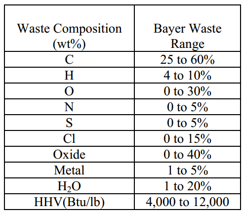
Table 1: Range of heterogeneous properties of medical waste.
PGM technology has been developed over the past 20 years. A 40-50 kg/hr pilot plant for processing of mixed radioactive wastes with up to 40-50% of incombustible components has been tested in the State Unitary Enterprise “MosNPO Radon”, which is based on a shaft furnace with plasma heating in pyrolysis conditions. The results of preliminary testing lead to the design and construction of an experimental industrial-scale facility for plasma processing of mixed radioactive wastes. The system was commissioned in Q4 2002 with an output of 200-250 kg/hr.
In 2007 an industrial scale demonstration PGM plant was built in Israel (figure 1) by Environmental Energy Resources, Ltd. (EER). The demonstration plant has been used to perform a series of trial runs to investigate the characteristics of the PGM process with different kinds of solid waste. After successfully operating the Iblin plant, EER began launching the PGM technology for processing MW. For this purpose, EER has teamed with Envitech, Inc., a San Diego based company that provides a proven solution for treating the off-gas from the PGM process. The Envitech Air Pollution Control System has been used on wide range combustion processes including, medical waste incinerators, thermal oxidizes, industrial dryers, fluidized bed reactors, and gasifiers. This paper will discuss how these technologies are combined to create an economically viable and environmentally friendly solution for converting medical waste into energy.
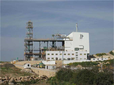
Figure 1: Picture of the PGM Iblin Plant
MEDICAL WASTE PROJECT DESCRIPTION
The medical waste treatment plant will use PGM technology to convert medical waste into a Syngas and a benign residue. Both system output materials may be considered as essentially secondary materials since they have commercial use in other processes. Due to the high calorific value of the Syngas, it may be recycled to a number of different products. Current plans include the production of steam or heat (Figure 2). A second option is the production of electricity (Figure 3). In both options, the products will be sold as commodities to nearby industrial users (as heat) or used by the plant as electricity with the surplus of electricity sold to the regional electric grid if this is considered to be advisable. The final decision of the secondary materials to be produced will be made based on financial, economic, and technical considerations.

Figure 2: PGM Steam/Heat Production Option
In both product options mentioned above the Syngas is produced in the PGM vessel. Once produced in the reaction vessel it is transferred to a thermal residence chamber to assure the destruction of dioxins and other hazardous materials. Due to the high calorific value of the Syngas, minimal amounts of fossil fuel (such as LPG or NG) are required to safely assure the ignition of the Syngas.
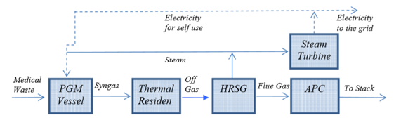
Figure 3: PGM Electricity Production
The off-gas from the thermal residence chamber enters a Heat Recovery Steam Generator (HRSG), a boiler that utilizes the heat from the process to produce superheated steam. The flue gas leaving the HRSG will enter an Air Pollution Cleaning (APC) system where it is cleaned to meet all Maximum Achievable Control Technology (MACT) requirements. If the production of electricity is desired, the steam from the HRSG enters a steam turbine through which electricity will be generated. The electricity will be used to run the plant with the additional option of selling it to the grid if this is judged to be advisable. If the production of heat is desired, the steam from the HRSG is sold to consumers who would be located in the vicinity of the plant.
PRINCIPLES OF THE PGM PROCESSING TECHNOLOGY
The PGM technology is a fixed-bed, updraft countercurrent plasma driven gasification system. The plasma torches, at the lower end of the vessel supply the heat for the different chemical processes which occur in the vessel. The Syngas generated exits the vessel at the top. Samples of the Syngas composition are shown in Table 2. The vitrified solid residue exits the vessel at the bottom, where it will be cracked to small gravel-like size using a standard water cracking system. A schematic of the PGM vessel is provided in Figure 4.
One of the key advantages of the system is that a full column of waste is kept inside the vessel at all times. The height of the column is controlled by automatic level indicators. This is one of the key features which cause the PGM pollutant load to be several orders of magnitude lower than that of other existing technologies.
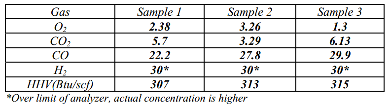
Table 2: Representative syngas composition from PGM Demonstration plant analysis of samples conducted by MODCON (Vol%).
The Four Zones of Reaction
There are 4 distinct zones of reaction in the process. All zones support each other and thereby render the operation of the process optimal. As the secondary material moves downward it passes through four distinct reaction zones:
- Drying Zone. This is where the moisture from the waste is evaporated.
- Pyrolysis Zone. Where the putrescible organics are converted into a pyrolytic gas, which together with the gasification products form a fuel gas (Syngas), which is evacuated from the reactor to be used in subsequent stages of the process.
- Gasification Zone. Where the introduction of oxidizing agents brings about the gasification of the char. This produces mainly CO and H2, which rise to “join” the pyrolytic gases and enrich their overall CV (Calorific Value).
- The Melting Zone. Located in the lower part of the reactor vessel, plasma torches form an electric arc. The air flowing through the torch is ionized, forming a Plasma jet, which extends beyond the tip of the torch. The plasma jet may reach up to 6000oC and, being submerged under a column of waste, melts the inorganic fraction of the wastes which reach the lower part of the reactor. The actual melting/vitrifying of the inorganics occurs at 1300oC to 1500oC.
The syngas exiting the PGM vessel is transferred to a thermal residence chamber where it has a residence time of at least 2 seconds at 1100oC to assure the complete destruction of dioxins. It, therefore, complies with the stringiest US EPA and EU regulations.
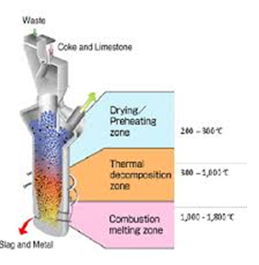
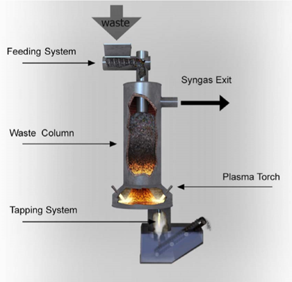
Figure 4: Schematic of the PGM Reaction Vessel
DETAILED DESCRIPTION OF THE PGM PROCESS
The waste is introduced at the top of the PGM vessel via a specialized feeding system designed for the feed of medical waste. The feeding system also assures that almost all air in the waste stream is removed prior to insertion into the vessel. The waste descends down the vessel by gravity. At any given moment, the vessel has a full column of waste through constant feed controlled by the use of level indicators. As the waste descends in the vertical shaft, it is contacted counter currently with hot gases exposed to the radiant heat of the refractories. Due to the rising temperatures, the waste undergoes several chemical processes. The first reaction is in the drying zone where free moisture is extracted from the waste. The gas emitted in this zone is mainly steam and hot water. The temperature in this zone is as high as 350oC . The destruction of the microbiological activity occurs in this zone.
The gasification reactions occur in an oxygen-starved environment. Residual air from the plasma torches and steam are fed into the gasification zone and react with the char (the residue from the pyrolysis zone) forming mostly CO and H2, which rise to mix with the rest of the gaseous products, as previously described. The gasification, partial oxidation of carbon, takes place between 900-1400oC and converts all existing carbon, leaving only the inorganics to move further down into the highest temperature zone which is the melting zone. As previously stated, when the inorganic residues of the secondary material reach the melting zone, the temperature to which these are exposed is produced by the plasma jets and maintained at about 1400-1650oC. This temperature melts the inorganic portion of the secondary materials and upon cooling, the melt solidifies to a glassy solid, the vitrified slag.
The plasma power system maintains the temperature profile distribution in the melting chamber, simplifying the draining of the molten slag, which is periodically discharged. The plasma torch system also allows the transition into an idling mode whenever it is desired to temporarily stop the processing of the secondary material. The control system maintains the melting chamber temperature automatically and requires no operator presence while in idle mode. If the computer control system detects a parameter out of acceptable range, the control system automatically notifies an operator who can respond via a remote telecommunication link, if minor adjustments are needed, or physically return to the plant if so required. Some of the basic chemical reactions are indicated in table 3. These equations provide a simplified description of the chemical reactions which take place in the process.

Table 3: Mean chemical reactions for the gasification and pyrolysis phases
The reactions associated with more complex hydrocarbons and halogenated hydrocarbons introduce other constituents to the reactants and final products. However, the CO and H2 formation are common to all secondary materials and form the primary ingredients of Syngas.
Some CO2 and minor quantities of CH4 are also produced depending upon the specific secondary material stream and PGM operating conditions. More complex organic materials react similarly. The plasma torches supply the heat necessary to melt the inorganic materials which are then incorporated into a molten glass bath and finally tapped out and solidify as a glassy substance. The plasma torches are completely independent and fully automated giving the operator maximum control over the process. The glassy solid residue immobilizes most hazardous metals (as oxides) into a leach resistant glass. Extensive leachability testing of this glass has been done in Israel and Russia using TCLP, CALWET, and EN-472 (the EU directive leachability test) testing methods. The tests were conducted to establish the key environmental and operational features of the slag.
Partial oxidation (Table 3, Equation 3) is used to supply some of the energy, together with the excess heat from the plasma torches, required by the endothermic pyrolysis & gasification reactions. Steam, not air, is used for the gasification process in order to maintain the high energy content of the Syngas. The resulting Syngas mixture has an energy content of > 250 Btu/SCF as shown in Table 2
Recyclable Products
The PGM process generates basically two recyclable products.
- A Syngas fuel which has a high calorific value;
- The melted inorganics which form a vitrified (glassy) slag in which undesirable materials such as heavy metals are trapped so that the slag is inert, meeting the most demanding standards such as the TCLP Standards (Toxicity Characteristics Leachability Protocol) and other leachability testing protocols.
Both products may be classified as secondary materials since they have a commercial value to other industries. The Syngas samples shown in Table 2 were taken during the operation of the PGM gasification system in Northern Israel and at the Radon Institute in Russia.
AIR POLLUTION CONTROL SYSTEM (APC)
Figure 5 shows a system arrangement for the APC system. Hot flue gas from the upstream HRSG is first cooled to saturation in an evaporative quencher. The quencher is designed as a low-pressure drop Venturi. It both quenches the gas and collects large particulate. After the quencher, the gas passes through a packed bed condenser/absorber for acid gas removal and sub-cooling. In this step, any HCl or SO2 in the gas stream is neutralized using a caustic solution. Although not considered a particulate removal device, the condenser/absorber will remove between 10% to 15% of the inlet particulate.
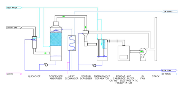
Figure 5: APC system arrangement
The final process step is the removal of the remaining particulate in the gas stream with a Venturi scrubber. Water condenses on particles due to sub-cooling in the condenser/absorber, causing their mass and diameter to increase, and enhancing particle removal. As a result, particulate entering the Venturi is less than 3 microns, and this allows the particles to be collected at a lower pressure drop.
Figure 6 shows a comparison of modeling results for Venturi particle removal efficiency versus particle size for 2 different cases with sub-cooling and no sub-cooling. Both cases show that removal efficiency for particulate less than 3 microns is dependent on particle size. That is because Venturi scrubbers collect particles primarily according to their aerodynamic size through inertial mechanisms between the water droplets and particles in the Venturi’s throat. As particles get smaller in the submicron range, they are able to find slipstreams between water droplets and avoid capture. Higher pressure drop can off-set this effect by increasing the differential velocity between the particles and water droplets. The difference between the sub-cooling curve and no sub-cooling curve shows the increase in removal efficiency for various particle sizes. For instance, a 0.5 micron particle will be removed with about 60% efficiency without sub-cooling. That compares to greater than 90% removal with sub-cooling.
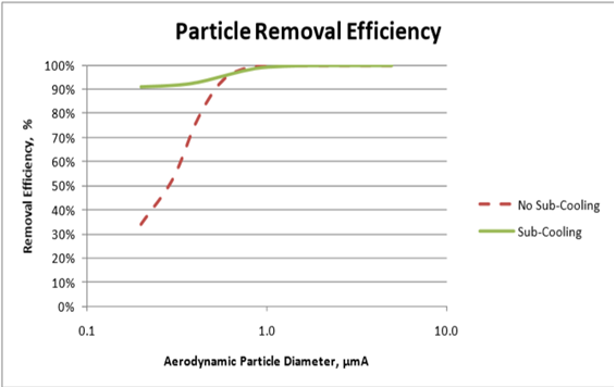
Figure 6: Venturi scrubber particle removal efficiency comparison by pressure drop and sub-cooling
The Venturi scrubber is followed by a horizontal, chevron style entrainment separator to remove the water droplets from the gas stream. The entrainment separator serves as the sump for the Venturi scrubber recirculation. A blowdown steam from the Venturi is purged to the C/A sump so there a single liquid discharge from the system.
In some cases, the particle size distribution and the outlet emission requirements may exceed the capability of a Venturi scrubber. In this case, an additional particulate polishing step is required. This can be done with a final polishing step using either a wet electrostatic precipitator (WESP) or a slight re-heat and a filter. With a polishing step, greater than 99% particulate removal efficiency can be achieved.
CONCLUSION
EER’s PGM technology provides a comprehensive solution to the medical waste management ever-growing problem. The PGM solution is environmentally friendly with a long and proven track record in dealing with various types of solid waste both hazardous and benign. Testing at the demonstration plant in Iblin, Isreal, confirms the technology is ideally suited for converting medical waste into a high yield Syngas and a benign solid residue suitable for construction materials. This concept is used in current plans for a medical waste treatment plant to produce steam or heat that will be sold as commodities to nearby industrial users. The Envitech air pollution control (APC) system will be used for post-process gas cleaning. The APC system uses a wet scrubber system that has successfully achieved low emission standards on similar processes, including exhaust gas from medical waste incinerators. The combination of the two companies are able to address the many challenges of delivering a sustainable medical waste disposal system.
REFERENCES
- http://www.who.int/immunization_safety/waste_management
- Gordon McKay. Dioxin characterization formation and minimization during municipal solid waste (MSW) incineration: Review. Chemical Engineering Journal 86 (3), pp. 343-368, 2002.
- K. Suksankraisorn, S. Patumsawad, B. Fungtammasan. Combustion studies of high moisture content waste in a fluidized bed. Waste Management 23 (5), pp. 433-439, 2003.
- Carlton C. Wiles. Municipal solid waste combustion ash: State-of-the-knowledge. Journal of Hazardous Materials 47 (1-3), pp. 325-344, 1996.
- Floyd Hasselriis, Anthony Licata. Analysis of heavy metal emission data from municipal waste combustion. Journal of Hazardous Materials 47 (1-3), pp. 77-102, 1996.
- Q. Zhang, L. Dor, K. Umeki, W. Yang, W. Blasiak. Process modeling and performance analysis of a PGM gasifier. 10th Conference on Energy for a Clean Environment. Lisbon, Portugal, 2009.
- Crawford, M. Air Pollution Control Theory, 1976.
- Calvert, S.; Englund, M. Handbook of Air Pollution Technology, 1984
Source:
Liran Dor, Andrew C. Bartocci. Environmentally Friendly Medical Waste Recycling Using Plasma-Gasification-Melting (PGM) and Wet Scrubbing Technology.